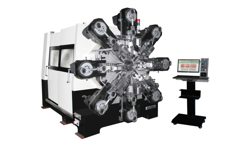
Special design equipped with:
• Servo Feed
• Rotary Wire
• Rotary Quill
• Single Spinner
• Optional Second Spinner
• 8 Servo Slides
• Optional X-Y Slide (X-Y free arm that moves perpendicular to servo slide – 5.0mm Max Wire Limit)
A special Camless design equipped with custom tooling enables our series of spring machines to easily produce a variety of springs and wire forms.
Utilizes double rail guides to facilitate lasting accuracy on slide movements.
Advanced attachments such as an x-y free arm and a second spinner tool can be optionally equipped.
Machine architecture provides automatic fault detection and warning system.
Dual spinner support and an x-y free arm attachment add versatility to setups.
Cam Machine without Wire Rotation
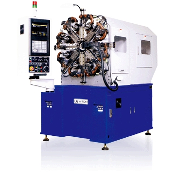
Cam Machine with Wire Rotation
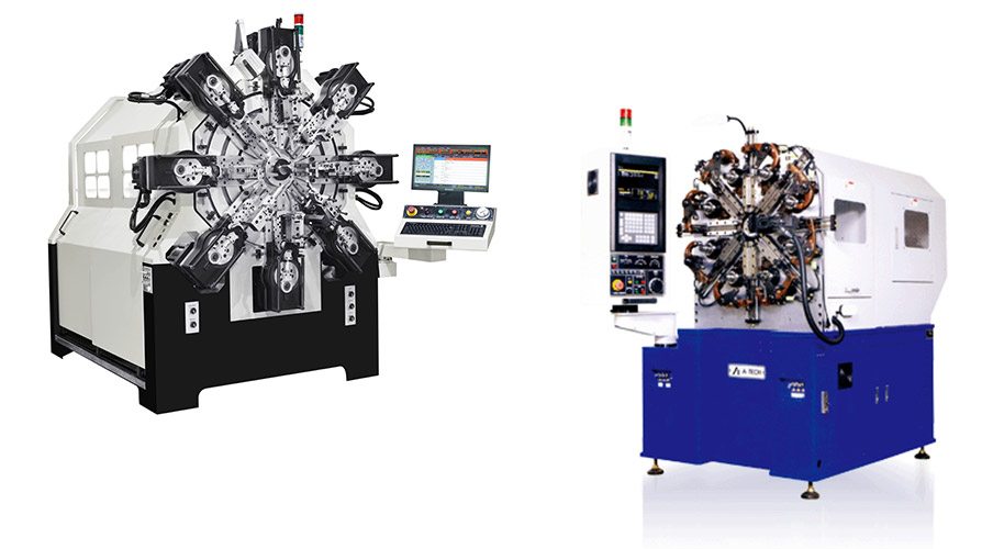
Camless without Wire Rotation
Camless with Wire Rotation
Cam Machine with Wire Rotation
3.2.1 AT-S20Wire Dimension Range 0.50-2.00 mm, 5 Axes
3.2.2 AT-S35Wire Dimension Range 1.20-3.50 mm, 5 Axes
3.2.3 AT-S50Wire Dimension Range 2.00-5.00 mm, 5 Axes
3.2.4 AT-S65Wire Dimension Range 2.60-6.50 mm, 5 Axes
3.2.5 AT-S80Wire Dimension Range 3.50-8.00 mm, 5 Axes
Camless with Wire Rotation
3.2.6 AT-M25Wire Dimension Range 0.40-2.50 mm, 15 Axes
3.2.6 AT-M40Wire Dimension Range 1.00-4.00 mm, 15 Axes
3.2.7 AT-M60Wire Dimension Range 2.00-6.00 mm, 15 Axes
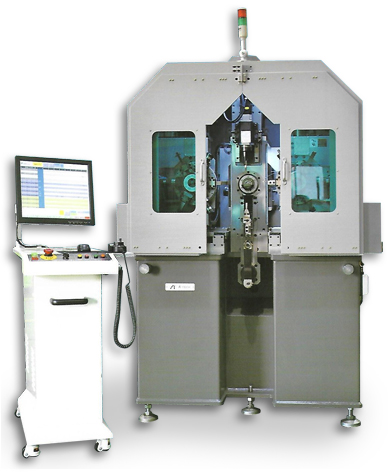
Special Wire Former
3.2.8 AT-TH20 Wire Dimension Range 0.50-2.00 mm, 17 Axes
3.2.9 AT-TH40 Wire Dimension Range 1.60-4.00 mm, 17 Axes
what is wire Forming?
Wire forms is a term that incorporates many shapes, textures and dimensions. The forms are engineered in two or three dimensions and commonly generated from wire and sometimes from tube. Typically, the raw stock for wire forms is fed off a coil that can weigh as much 5,000 pounds (2,300 kg) or as little as five pounds (2.3 kg). In some cases, the raw material commences production in blank forms that are fed from a hopper.
Wire forming may be defined as any length of wire that has had some force applied to it that changes the shape of the wire. Wire can be round, flat, hexagonal, square, oval, triangular, elliptical, or D- shaped, just to name a few. Wire can be made of low-carbon steel, medium- carbon and high-carbon steel. It can also be made of stainless, aluminum, copper, brass and an assortment of alloyed materials.
Wire can be formed by applying a force that changes its contour. It may be bent, punched, swaged, spanked, pierced, chamfered, sheared, cold formed or headed, along with other techniques. A myriad of secondary operations are available: punch, cut, bend, stamp, form, head and coin the wire to create the desired shape.
These forces may be applied by a number of different means. A simple, hand method using a lever and a spindle can produce a number of different forms along with simple air benders, hydraulic benders, presses and dies, four slide machines, up to high- volume, 3D CNC programmed benders. Volumes, tolerances, chemical and mechanical characteristics, design configuration, and intended use help determine the best method of forming. The desired wire form will be based on what the end product is and what it must do.
The ingenuity of the methods to manipulate the material is stunning. This article will cover the breadth of wire forming options, with pictures to add clarity for the manufacturing engineer trying to get his/her arms around a vast and important topic.
How It Started
Forming is typically created in a continuum, from a dedicated tool that is very fast but takes significant investment and time to set-up, to a range of options that are more nimble with slower production speeds.
The process of bending wire forms began by manually bending a wire around an anvil and a post. Manual benders then became mass-produced by companies like Diacro, which built robust units where many bending operations could be done with preset pins. These machines were plagued with a lack of consistency since operators got tired over time and did not bend the handle fully, which resulted in poor quality. In addition, as labor became expensive, more productive means were required to be competitive.
Later, companies like Penn Machinery built hydraulic benders to bend two or three wires at a time. This tripling in productivity was beneficial, but the march of progress required faster speed and better quality. To increase production speeds, four slide machines came into vogue to mass produce wire forms utilizing mechanical tooling and enabling higher production rates of simple wire forms. However, a big drawback of four slides was the inability to complete a quick changeover or slight modifications to the end product without a new tooling set.
Examples are four slide machines made by Finzer, Bihler or Nilson. These machines can make over 3,500 simple wire forms consistently in an hour with a one-time tooling investment of dedicated dies. Sophisticated four slide die makers try to make tools that have universal applications as much as possible to improve tool production turnaround. Die makers of this caliber are harder to find and train.
A more nimble approach, because fewer dedicated tools are needed, are computer numerically controlled (CNC) two-dimensional or three-dimensional bending machines. These machines take less than an hour to changeover from one wire form project to another as opposed to the weeks it takes to make four slide tooling.
CNC benders are manufactured worldwide by companies like AIM (Chicago, Ill.), Ultimat (UK), Whitelegg, (UK), Numalliance (France) and Wafios (Germany). AIM and Numalliance machines have the ability to download programs from AutoCAD software into the robot which saves programming time.
Numalliance has a nice system that allows one to “hand crank” a straightener rolling positioner
for quick changeovers of wire diameters. AIM has spearheaded integrating robots (they specialize in Fanucs) to do secondary tasks like punching, bending, and forming with the auxiliary robot. AIM’s machines are fast-feeding wire as fast as 495 feet per minute and bending wire 3600 degrees a
second with their blistering servo motors. Ultimat and Whitelegg specialize in two-dimensional bending that has an integrated butt welder in their product line so that frames can be welded closed without a secondary operation. Ultimat even has machines that can integrate welding flush “t-bar” ribs into a shelf frame off of a second coil integrated into the production cell.
For very long runs (over 5 million pieces) with minimal needs to changeover, Numalliance has created a machine that produces over seven thousand complex parts per hour. It utilizes elaborate hard tooling that creates parts in a parallel forming line linked to each other called a Numacell. The big drawback is the expensive tooling and time to changeover from one style of part to another part. If the runs are very long, the price and the lack of flexibility will be covered by the machine’s productivity.
How Does the Wire Forming Process Start?
The most common method of wire forming starts with wire in coil form. Wire forming requires the material to be straight so that wire forms are consistent. Eckehard Albert has stated that the process of straightening “is the apparent removal of stresses accumulated by a material due to the forces and moments applied to it in the course of its production.” Albert, famous for his leadership in the straightening industry, was a co-founder of Witels-Albert.
The most common way to straighten is with precisely machined rolls. The rolls are adjusted by a set-up operator or in more sophisticated factories with automatically adjusted CNC straightening.
Typically, the bottom rolls are fixed and the top rolls are adjusted. There are several ways to make adjustments on the rolls. One can use a rail adjustment or individual roll adjustments. The positioning
of each of the rolls against the zero line manipulates the wire to turn in different directions, so that
residual stresses in the coil are relieved.
Another method used to straighten wire is the rotary arbor, which can be seen in Wafios Benders and Lewis Straighten & Cut machines. This style of straightening does not use fixed straighteners, but instead uses rotating straighteners because they believe that it will create a straighter wire.
According to Witels-Albert, there are two types of stresses in wire: avoidable and unavoidable. Examples of avoidable stresses are overhead pull off, static spooling, incorrect deflecting, and frequent changes of direction and wrongly implemented straightening processes. One must make sure that avoidable stresses are not occurring so that the wire has a better chance of being straight.
Some unavoidable stresses occur during drawing, spooling, winding, deflecting, and guiding. Identifying a high-quality mill that provides consistent wire with the same helix and camber is critical. We have found suppliers like Taubensee, J&L, Sivaco and Mid-South Wire are able to provide this consistency.
Some imported material, although cheaper, does not have consistent properties throughout the coil. As a result of inconsistent wire, the machine operator needs to adjust the wire straighteners for proper wire “behavior” which is a time-wasting exercise that ties up key talent.
What are Different Ways to Form Wire Ends?
There are many ways to shape a wire form or the ends of a wire form. Some wire formers load material into dies with a hopper, which is the most common method. This involves an extra direct labor step to move wire from a Straighten Cut machine to the hopper. Several companies like Numalliance and AIM have incorporated a pick-and-place robot that is integrated with the secondary process.
The various wire form machines detailed above are specialized to form wire in two and three dimensions. Some of the machines can also form a variety of ends and interior geometry. Here are some common wire form techniques:
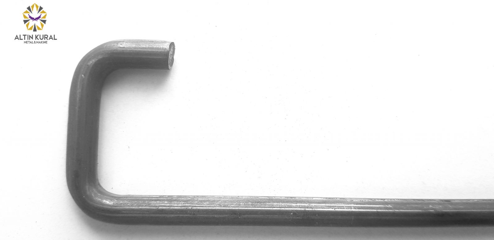
As Cut - This is the term for what the wire form looks like when the machine cuts the material with a die like a guillotine knife. It is sometimes called “Machine Cut.” Typically, this is the result after the machine has been straightened and cut off by a Lewis, RMG, or Shuster cut machine. The resulting burrs are very small (maximum +0.005” [0.13mm], which is hardly noticeable in most applications) and usually acceptable.
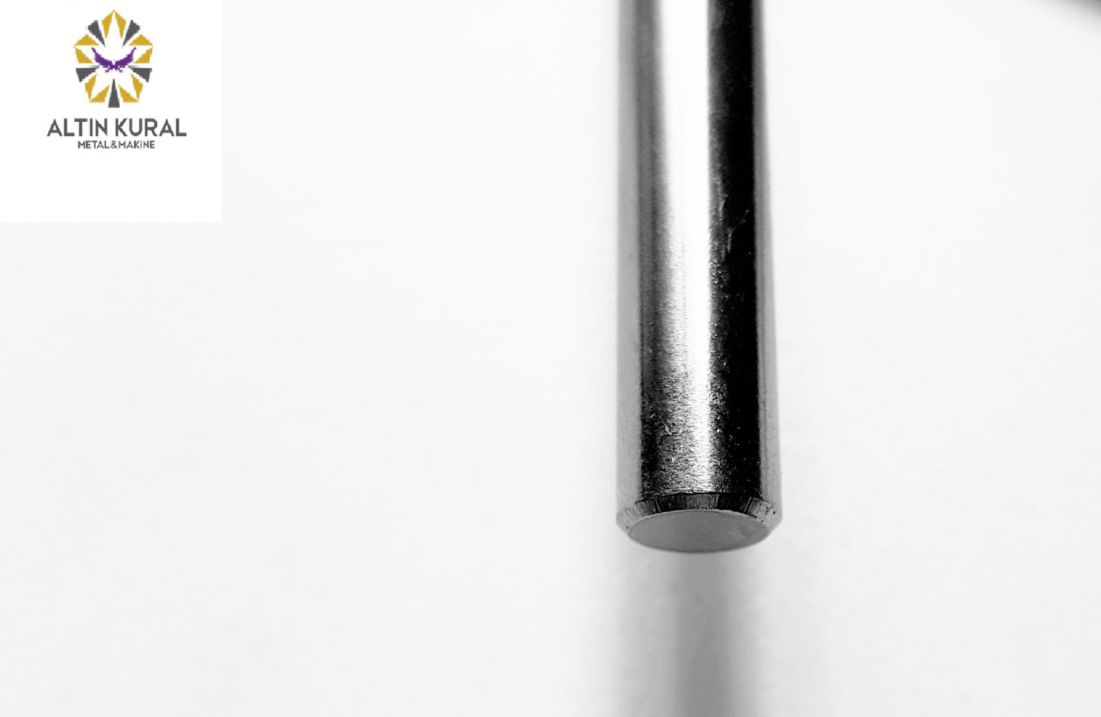
Chamfered or Deburred – This additional step is performed after the part has been cut, in order to remove any burr from the wire and thus make it safer
and smoother to the operator and the client. Deburring usually refers to grinding down the side with the burr. This picture shows a wire form with a uniform
deburring or grinding (or could be in a Lathe option). AIM and Latour have machines that can do this operation in-line, so that the part production is not delayed.
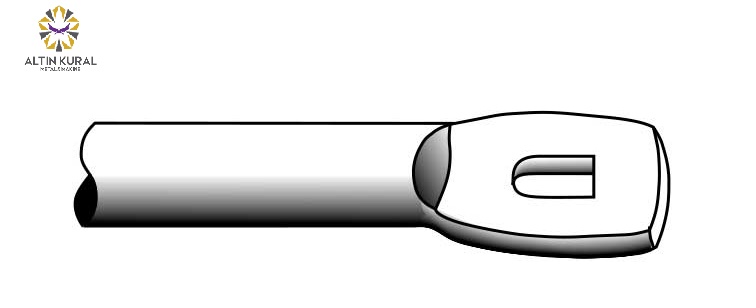
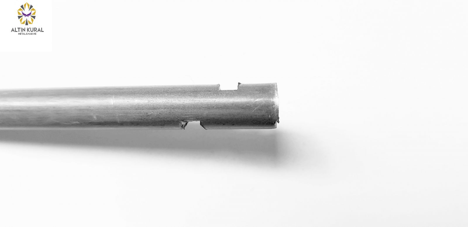
Swaging or Winging – Typically using a press, a die is used to push down on a wire, thus carving out (or hogging out) material and displacing the material.
Swaged & Pierced - This two-step process typically starts with a press and a special die that is pushed down on a wire, carving out material and displacing the material. Then a second die “pierces” out a hole through the material.
Specially-Shaped Holes – This two-step process typically starts with a press and a special die that is pushed down on a wire, carving out material and displacing the material. Then a second die punches-out out a specially designed hole through the material.
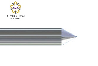
Pinch Point - With dies on the end of a punch, a pointed end is created similar to the bottom of a stake. This is a coarse approach but an effective way to create a sharp edge.
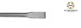
Diagonal Cut-Off or Chisel Point - This is a technique to make an end similar to a pinch point end, in which material is removed by a die in a punch operation in a jagged manner so that the end of the wire form is sharp and cut off in a diagonal slope or chisel point.
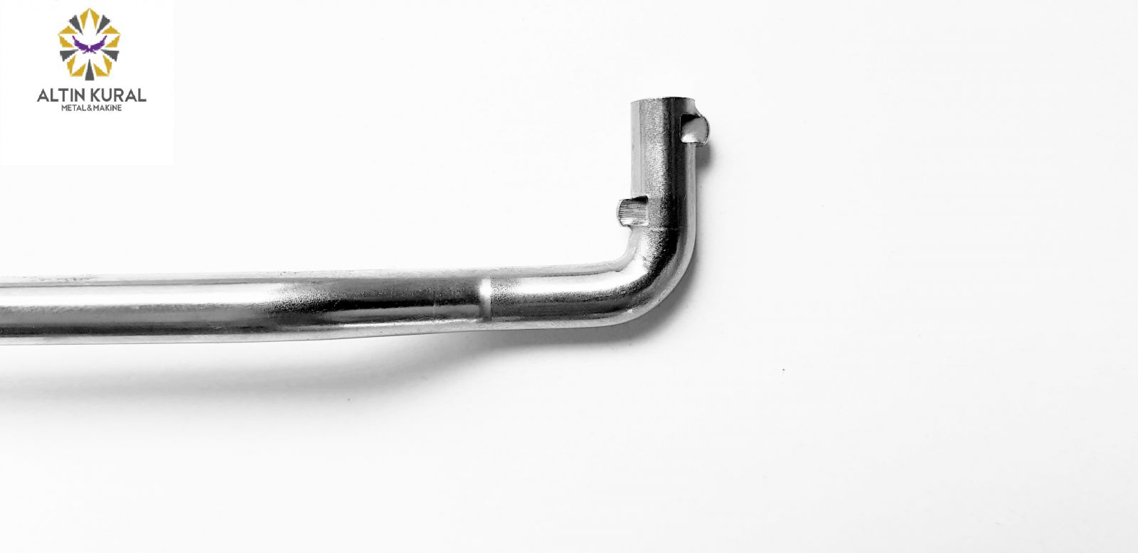
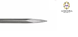
Turned End - With a lathe or roller dies, this end is created with a smooth, pointed end. This method is similar to chamfering except that it produces a smaller angle and a larger flat spot.
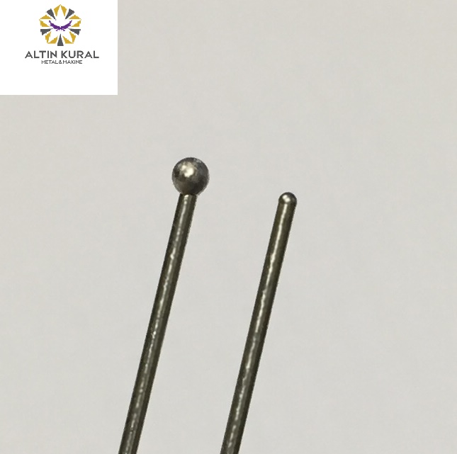
Ball End - The end of the material is formed into a ball typically by a lathe operation.
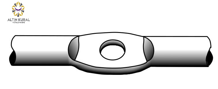
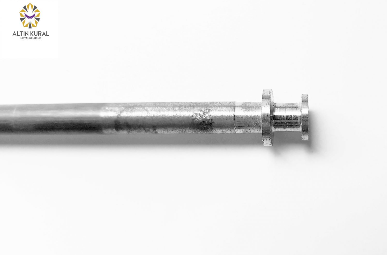
Grooved - Typically used to hold a retaining ring, grooved material is lathed out of the wire. This results in a continuous piece of wire carved into three adjacent wire forms of different diameters. The picture adjacent to this description, demonstrates one of many different grooving techniques that are available to the client.
Heading or Cold Heading - Heading is a process in which material is formed by a pair of gripping dies which grab material (wire typically) to form a carriage out of the wire. This operation holds
the material tight before the next violent action occurs--a punch smashes down on the gripped
wire that is being held tightly by the gripping dies. This results in a round or a flat head formed by the punch, creating a rounded bolt or a flat screw top. This is how nails are made.
 (0216) 577 54 40